The articles in the past explain the following.
- Introduction of the dynamics of an omni-wheel robot
- LQR controller implementation and simulation result
Omni-wheel
I chose this omni-wheel since it is cheap (660 yen for each). Its radius is 24 mm.

Motor
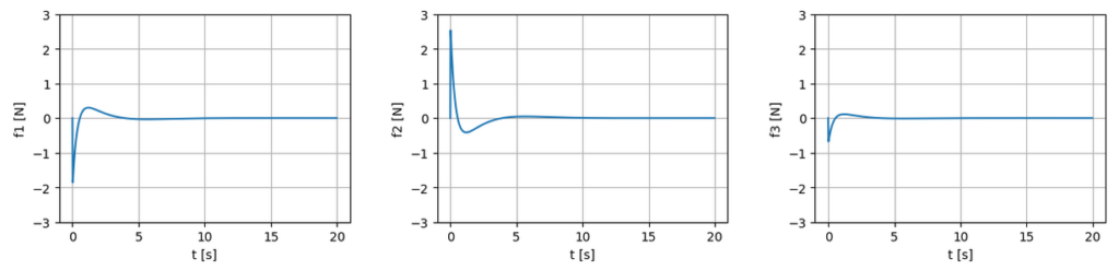
Force for balancing a pole
Based on the simulation result, the motor needs to exert $2.5 \, \mathrm{N}$ at maximum. The simulation is conducted here.
Here, we assume the following physical parameters.
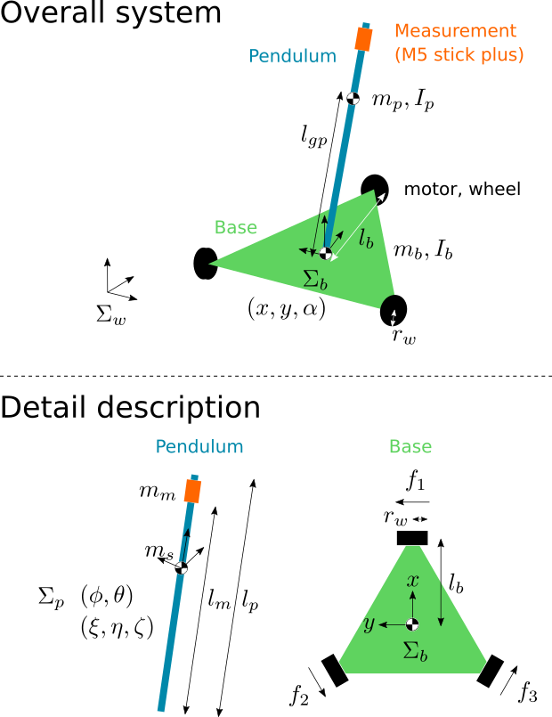
| $m_b$ | mass of omni-wheel robot body | $1.0 \, \mathrm{kg}$ |
| $l_b$ | length between wheel and the center of mass | $0.12 \, \mathrm{m}$ |
| $r_w$ | radius of omni-wheel | $0.024 \, \mathrm{m}$ |
| $I_{b,zz}$ | Inertia of omni-wheel robot body about $z$ axis | $0.0035 \, \mathrm{kg \cdot m^2}$ |
| $m_p$ | mass of pendulum | $0.01 \, \mathrm{kg}$ |
| $l_p$ | length of pendulum | $2.0 \, \mathrm{m}$ |
The mass of the omni-wheel robot body is estimated from the information
- motor mass: $0.1 \, \mathrm{kg} \times 3 = 0.3 \, \mathrm{kg}$ (It varies depending on the chosen motor)
- battery mass $0.023 \mathrm{kg} \times 12 = 0.276 \, \mathrm{kg}$
- wheel mass $0.039 \, \mathrm{kg} \times 3 = 0.117 \, \mathrm{kg}$
, whose sum equals to $0.693 \, \mathrm{kg}$. Considering the mass of the circuit board and the omni-wheel body frame, I assume that the total body mass is about $1 \, \mathrm{kg}$.
Regarding the wheel’s radius $r_w = 0.024 \, \mathrm{m}$, the maximum torque we need is $\tau_b = 2.5 \times 0.024 = 0.06 \, \mathrm{Nm}$.
Friction force
Also, friction force should be considered. Referring to this website, the rolling friction coefficient would be around $\mu$ = 0.02 (I referred to the value for “car tires on tar or asphalt”).
The friction force the robot needs to exert is calculated as $\mu m_b g$. Here, $m_b = 1.0 \, \mathrm{kg}$ is the robot’s weight, and $g = 9.8 \, \mathrm{m/s^2}$ is the gravitational acceleration constant.
\begin{align}
\mu m_b g = 0.02 \times 1.0 \times 9.8 = 0.196 \fallingdotseq 0.2 \, \mathrm{N}
\end{align}
Required torque is calculated by multiplying $r_w$.
\begin{align}
\tau_f = r_w \times \mu m_b g = 0.024 \times 0.196 = 0.0048 \fallingdotseq 0.005 \, \mathrm{Nm}
\end{align}
In total, we need around $\tau = \tau_b + \tau_f = 0.065 \, \mathrm{Nm}$.
Wheel Velocity
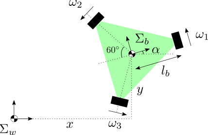
For the calculation of each wheel velocity, utilize the following equation.
\begin{align}
\begin{bmatrix}
\omega_1 \\
\omega_2 \\
\omega_3
\end{bmatrix} =
\begin{bmatrix}
0 & 1 & l_b \\
-\frac{\sqrt{3}}{2} & -\frac{1}{2} & l_b \\
\frac{\sqrt{3}}{2} & -\frac{1}{2} & l_b
\end{bmatrix}
\begin{bmatrix}
\cos \alpha & \sin \alpha & 0 \\
-\sin \alpha & \cos \alpha & 0 \\
0 & 0 & 1
\end{bmatrix}
\begin{bmatrix}
\dot{x} \\
\dot{y} \\
\dot{\alpha}
\end{bmatrix}
\end{align}
The left $3 \times 3$ matrix converts velocity from the body frame to the wheel frame, and the right $3 \times 3$ matrix converts velocity from the world frame to the body frame.
This paper explains the kinematics of an omni-wheel robot in detail.
During the simulation, the wheel velocity is found to be less than $1.0 \, \mathrm{rad/s} = 9.54 \, \mathrm{rpm}$. Revolutions per minute (rpm) is calculated by $\omega_{\mathrm{rpm}} = \frac{60 \times \omega_{\mathrm{rad/s}}}{2 \pi}$ or by this website.
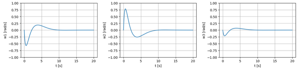
We have come to the conclusion that revolutions per minute is at most $10 \, \mathrm{rpm}$.
Comparison
The following table shows the four motor candidates.
| Model number | GA25-371 $400 \, \mathrm{rpm}$ | GA25-371 $250 \, \mathrm{rpm}$ | GB12-N20B $155 \, \mathrm{rpm}$ | GB12-N20B $105 \, \mathrm{rpm}$ |
| Rated voltage | $12 \, \mathrm{V}$ | $12 \, \mathrm{V}$ | $6 \, \mathrm{V}$ (range: $3 \, – \, 12 \, \mathrm{V}$) | $6 \, \mathrm{V}$ (range: $3 \, – \, 12 \, \mathrm{V}$) |
| Reduction ratio | $19$ | $21$ | $100$ | $150$ |
| No-load speed | $400 \, \mathrm{rpm}$ | $250 \, \mathrm{rpm}$ | $155 \, \mathrm{rpm}$ | $105 \, \mathrm{rpm}$ |
| Rated torque | $0.264 \, \mathrm{Nm}$ | $0.421 \, \mathrm{Nm}$ | $0.068 \, \mathrm{Nm}$ | $0.098 \, \mathrm{Nm}$ |
| Rated speed | $230 \, \mathrm{rpm}$ | $140 \, \mathrm{rpm}$ | $90 \, \mathrm{rpm}$ | $60 \, \mathrm{rpm}$ |
| Hall feedback resolution | $234.3$ | $374$ | $198.6$ | $301.9$ |
| Weight | $0.099 \, \mathrm{kg}$ (ref | $0.099 \, \mathrm{kg}$ (ref | – | – |


All of them suffice the requirement
- the maximum torque should be larger than $0.065 \, \mathrm{Nm}$.
- the maximum wheel velocity should be larger than $10 \, \mathrm{rpm}$.
For example, if we use GA25-371 at $400 \, \mathrm{rpm}$, the wheel can move at a speed of $1.0 \, \mathrm{m/s}$. This results in a translational motion speed of $0.87 \, \mathrm{m/s}$ (because of the omni-wheel robot’s structure, $\frac{\sqrt{3}}{2}$ is multiplied).
Torque unit conversion from $\mathrm{kg \cdot cm}$ to $\mathrm{Nm}$ is done here ($9.8 / 100 \, \mathrm{kg \cdot cm} = 1 \, \mathrm{Nm}$).
After all, I determined to buy GA25-371 $400 \, \mathrm{rpm}$ and GB12-N20B $155 \, \mathrm{rpm}$. Here, I prioritized the rotational speed of the motors.
コメント