I have summarized the functionality of each circuit component of ESP32-DevKitC V4 board in the previous article. This article checks if a pitch conversion board can work with a similar schematic to the devkit board. What we test is if writing Arduino code is successful and it works as expected.
I used the following pitch conversion board.

Hardware
Parts
The electrical parts used in this article are listed here.
| Component | Pieces | Role |
| ESP32-WROVER-B pitch conversion board SSCI-039987 | 1 | Microcontroller |
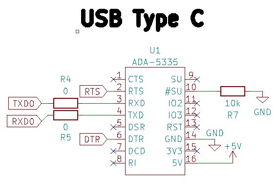
| CP2102N USB-C serial converter ADA-5335 | 1 | Convert signals from a PC to the board |
| Tactile switch | 2 | Manual button for EN and Boot pin |
| LED | 2 | Indication of status |
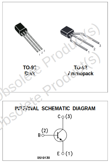
| NPN bipolar transistor PN2222A | 2 | Auto programming |
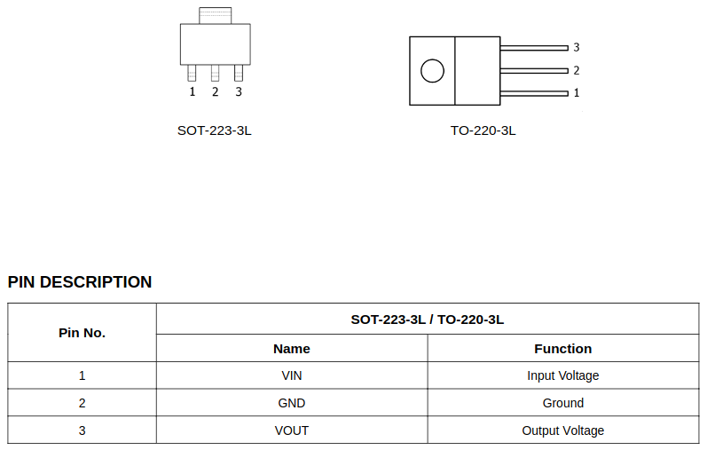
| $3.3 \, \mathrm{V}$ Regulator LM2940-3.3 | 1 | Regulate output voltage to $3.3 \, \mathrm{V}$ |
| Capacitor | $0.1 \, \mathrm{\mu F}$ x 3 $10 \, \mathrm{\mu F}$ x 2 $22 \, \mathrm{\mu F}$ x 1 | Remove noise Maintain voltage stability |
| Resistor | $0 \, \Omega$ x 2 $147 \, \Omega$ x 2 $10 \, \mathrm{k} \Omega$ x 4 | Current suppression |
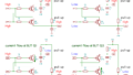
The bipolar transistor pin allocation is as follows.
The regulator one is shown here.
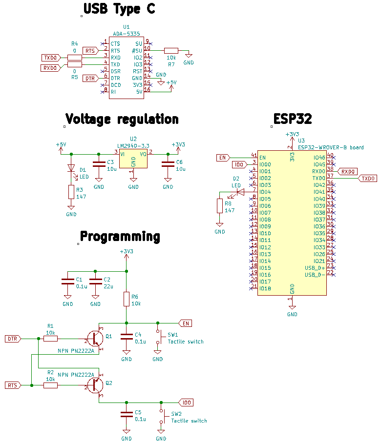
Schematic
My board schematic looks like this. Nearly the same as the official devkit board.
Software
This website shows us how to upload Arduino code to ESP32 devkit board in detail.
Initial setup
First of all, open “Boards Manager”.
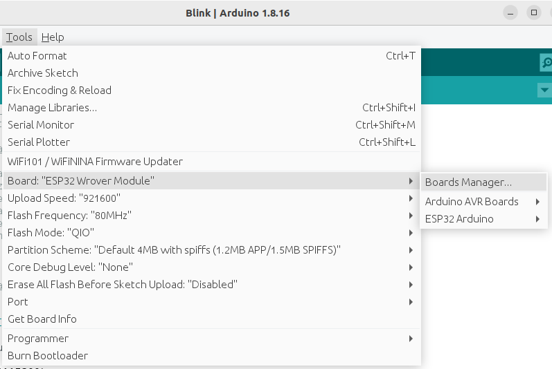
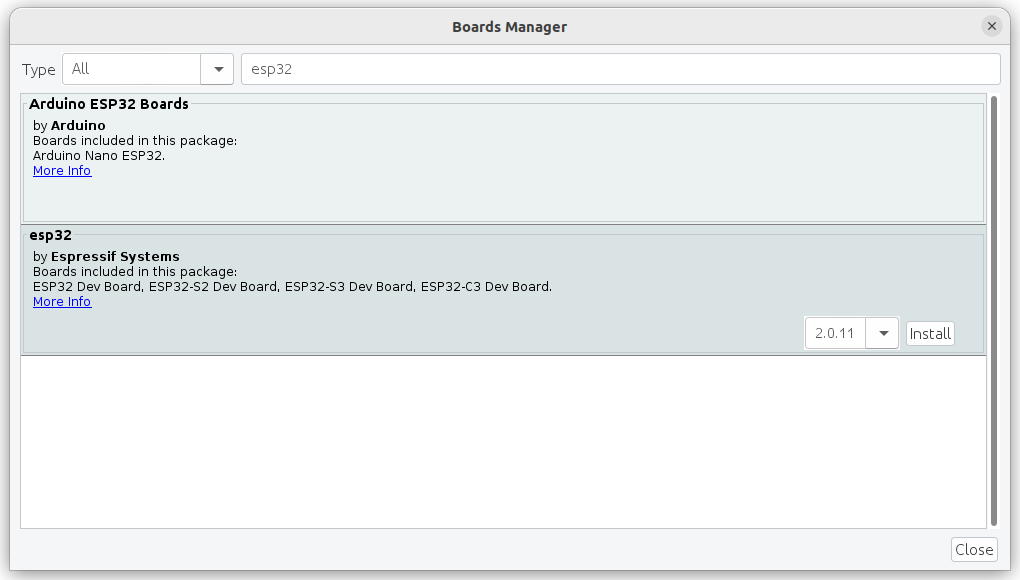
Then, search for esp32 and install the one from Espressif Systems on your Arduino IDE.
Code
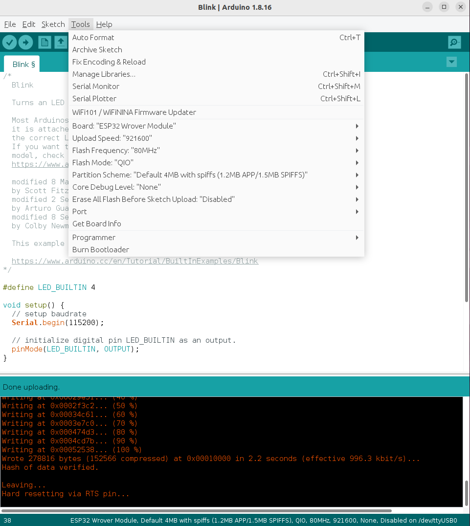
We use a straightforward code to blink an LED at GPIO4. As for the serial communication check, added a line to print “a”.
#define LED_BUILTIN 4

void setup() {
  // setup baudrate
  Serial.begin(115200);

  // initialize digital pin LED_BUILTIN as an output.
  pinMode(LED_BUILTIN, OUTPUT);
}

void loop() {
  // blink LED
  digitalWrite(LED_BUILTIN, HIGH);   // turn the LED on
  delay(100);                                                // wait for a while
  digitalWrite(LED_BUILTIN, LOW);    // turn the LED off
  delay(100);                                                // wait for a while

  // print a text on Serial Monitor
  Serial.println("a");
}
Upload
The following setting worked fine for writing Arduino code to my ESP32-WROVER-B module.
Result
The red LED blinks like this!
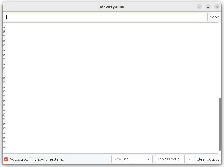
The serial communication works as well!
Furthermore, when we add an external voltage supply at the $5 \, \mathrm{V}$ line instead of the USB cable, the LED starts blinking as well on pressing the switch connected to the EN PIN.
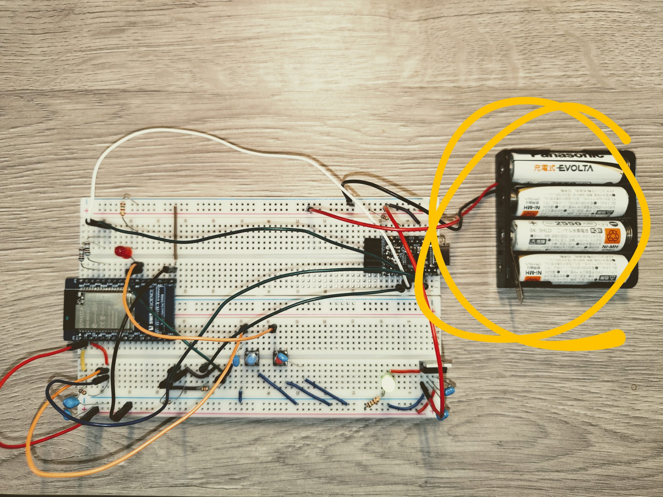
Summary
This article showed how to set up electrical components and write a simple code for the ESP32-WROVER-B pitch conversion board.
I found out that sometimes cannot write the source code to the module. This seems to be because of the breadboard’s instability. Hoping a PCB solves this issue and I will design one in the following article.
コメント