More than I expected, generating 3.3V from 3.7V seems difficult and there is no standard way. There are a bunch of discussions on this kind of topic.
- How to effectively regulate 3.3v from a 3.7v Li-ion battery
- How to get 3.3v from 3.7 Lipo battery?
- 3.7v to 3.3v voltage regulator [closed]
- Regulating LiPo battery to 3.3V
They had almost the same question as mine.
Hello, I want to power an ESP32 with 3.7v Lipo battery. The ESP32 is powered at 3.3v can’t handle the 4.2v – 2.7v that a Lipo battery typically outputs. I was thinking of just using a 3.3v voltage regulator, but I can’t use the rest of the battery after 3.4v – 3.5v even with a relatively low dropout voltage. I also thought about stepping the battery up to 5v then back down to 3.3v. Which do you recommend doing?
How to get 3.3v from 3.7 Lipo battery?
After looking through some articles, I learned that there are three methods for achieving voltage regulation.
- Use an LDO (Low Dropout) voltage regulator to get 3.3V
- Raise the voltage to 5V from 3.7V using a boost converter (a.k.a step-up converter) and regulate it by the usual voltage regulator.
- Utilize a buck-boost converter to stabilize the output voltage
LDO voltage regulator
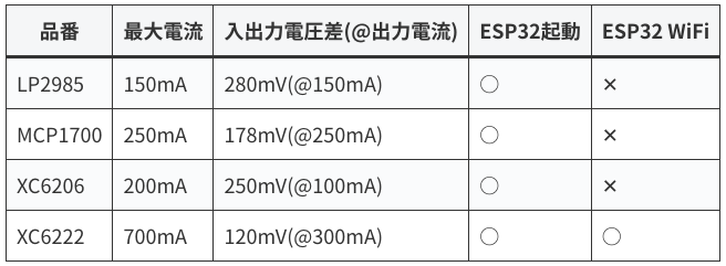
The following article explains how to use an LDO (Low Dropout) voltage regulator.
The article concludes that XC6222 was the only option out of 4 candidates in using ESP32 and its wifi functionality.
In some community sites, I could find lots of LDO parts introduced (ST1L08SPU33R / TPS73733 / AP2210K / TC2117 / TC1262 / MCP1700-3302E / MAX604).
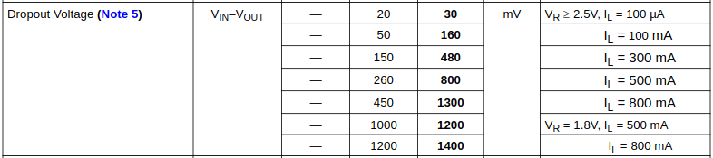
Still, the dropout voltage is too high for some LDO parts when the load current is high (the maximum dropout voltage permitted for a 3.7V LiPo battery is 0.4V = 3.7 – 3.3V). TC2117 datasheet shows the example; the maximum dropout voltage is 1.4V when the current is around 0.8A.
As described here, sometimes the ESP32 requires more than 0.79A.
It has also been observed that the chip draws more than 790 mA at times, particularly when both WiFi and Bluetooth are used simultaneously.
Insight Into ESP32 Sleep Modes & Their Power Consumption
Boost converter and a usual voltage regulator
This article uses a boost converter that steps up the LiPo battery voltage to 5V, and then connects it to the ESP32 board, which regulates the voltage to 3.3V.
However, using both a boost converter and a regulator has disadvantage in terms of battery life as described in the following comment.
Q. would stepping up 3.7v to 5v and then back down to 3.3v make my battery run time shorter than just using a voltage regulator 3.3v?
How to get 3.3v from 3.7 Lipo battery?
A. Of course the battery lifetime would be worse.
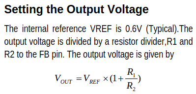
Boost converter parts recommended in a community website were MT3608 and MAX1724. MT3608 can generate arbitrary voltage based on the following equation.
Buck-boost converter
The following article shows the usage of a buck-boost converter.
The author mentions that ESP32 requires a voltage larger than 3.5V when it connects to wifi (he says only 2.9V was enough when putting additional resistor and capacitor).
The disadvantage of the buck/boost converters is stated as follows.
buck or buck/boost converters often have a quiescent current much higher than the low Iq LDOs that are ubiquitous these days.
Regulating LiPo battery to 3.3V
Recommended buck-boost converter were RT6150A/B, BD8306MUV-E2, TPS63051, MCP1253, and TPS63020.
A buck-boost regulator is the best choice, so you can exploit the full voltage range of the Li-ion cell. TI’s TPS63020 is a very good one. I would avoid LDOs, too, since they are far too inefficient for battery-powered devices.
3.7v to 3.3v voltage regulator [closed]
Comparison
The pros and cons of using each method are summarized in this table.
| Pros | Cons | |
| LDO voltage regulator | The circuit becomes simple with fewer components / its noise is very low | Dropout voltage becomes large when the current is high / produced heat gets large |
| Boost converter + voltage regulator | Can output a large amount of current without concerning dropout voltage | The circuit becomes complex / shorter battery life-expectancy |
| Buck-boost converter | Highly efficient even if Vin and Vout are largely deviated | The noise is large since it has an inductor in the circuit / the parts are expensive / much higher quiescent current |
These are excellent articles describing the difference between LDO and DC-DC converter.
- LDO/DC - DC コンバータのしくみと使い方
- Buck Converter Regulator vs LDO for DC, AC, and RF: Which is Best?
- When should you choose LDO or Buck Converter?
Buck converters and LDOs have their own upsides and downsides. If efficiency is not your priority, heat is not a concern, the current necessary is very small, or Vin is only slightly higher than Vout, an LDO can be used. But, if efficiency and performance are your utmost concern even if it is more complex and likely to be more expensive, then a buck converter is the ideal choice.
When should you choose LDO or Buck Converter?
Example circuit
I used electrical parts which are listed in the default KiCad library in the following examples.
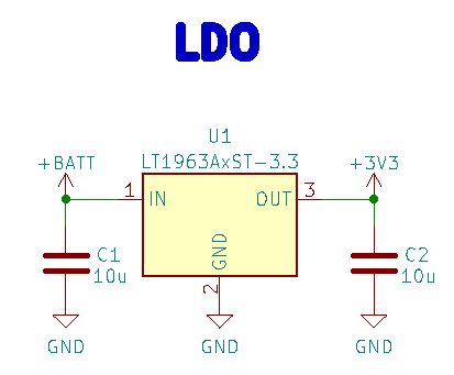
LDO
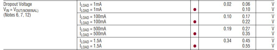
LT1963 should fit our purpose since the dropout voltage is low even when the load current is larger than 0.5A.
Appropriate capacitor values are addressed as 10uF in the datasheet. So, the example circuit should be like this to generate 3.3V.
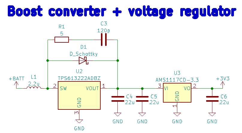
Boost converter and a usual voltage regulator
The following example circuit can be suggested when using TPS61322 for a boost converter. Refer to the detailed way of selecting resistor and capacitor values here. Use AMS1117 which regulates the voltage to 3.3V as in the ESP32-DevKitC V4 board.
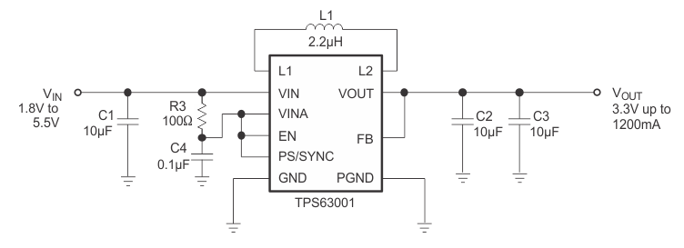
Buck-boost converter
We can use TPS63001 as a buck-boost converter. The example circuit design is shown below. Look through the detailed description here. The datasheet suggests using VLF4012-2R2 for an inductor L1.
.
The difference between PGND and GND is addressed as follows.
The Power-Ground (PGND) is used as the return current path for high power components while the Analog Ground (AGND) is used as the return current path for the control/logic… Note, however, that both PGND and AGND must be connected together at a single point.
The difference between Power Ground (PGND) and Analog Ground (AGND)
Summary
In this article, I have suggested three ways to generate 3.3V from a 3.7V LiPo battery. The information about the pros and cons of each method should be beneficial.
コメント