In the previous article, I posted an ESP32 remote controller PCB design using KiCad. Here, I summarize the way to order the PCB to PCBWay. Furthermore, I checked whether the PCB works well in this article. This project is sponsored by PCBWay.
Order
What is necessary for the order is summarized on the official site.
- BOM List
- Gerber file
- Centroid file
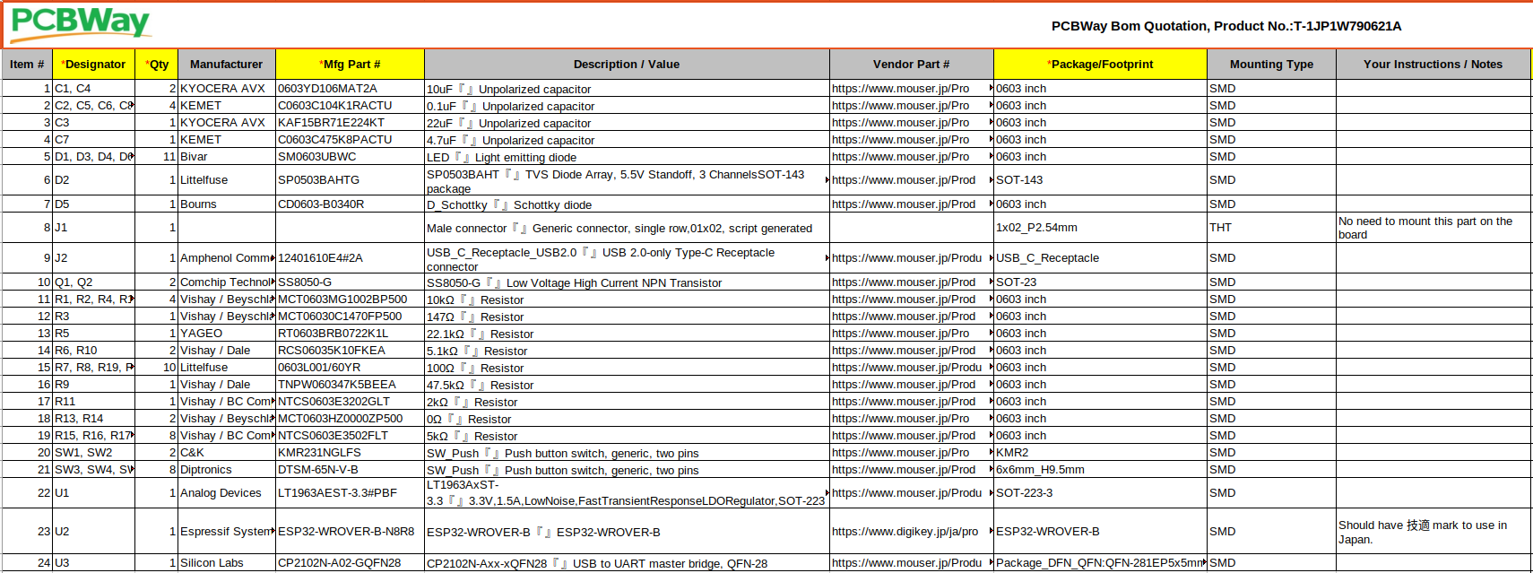
BOM list
According to the site, the BOM list should look as follows. You can find the .xlsx file for the remote controller here.
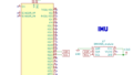
Gerber file
The following information is required for gerber files at least.
As a minimum request, PCB assembler needs the files of three layers: Silkscreen, Copper (Track) and Solder Paste.
Files Requested for PCBA
The procedure to output gerber files is described here in detail.
Centroid file
The definition of the centroid file is explained as follows.
Centroid is the special file for assembly used for quickly programming the assembly machines… The Centroid file describes the position and orientation of all the surface mount parts, which includes the reference designator, X and Y position, rotation and side of Board (Top or Bottom). Only surface mounting parts are listed in the Centroid.
Files Requested for PCBA
The procedure to output centroid files through KiCad is described here in detail.
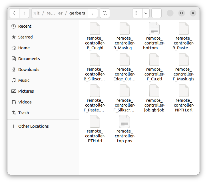
After executing these processes, the following gerber and centroid files are generated. You can find them here.
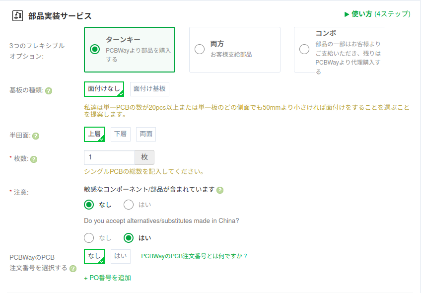
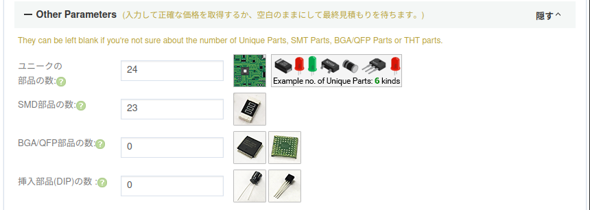
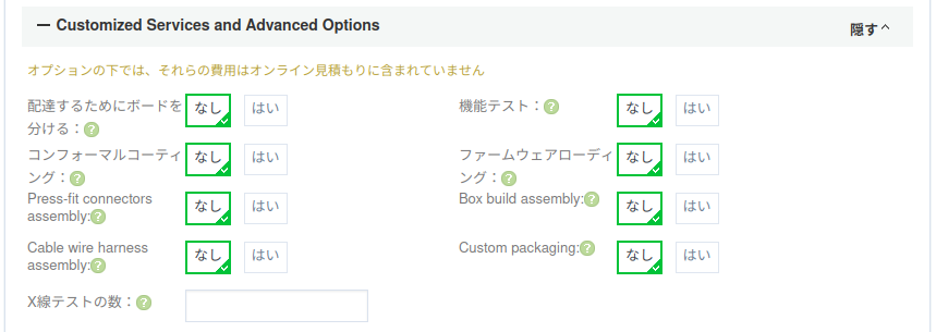
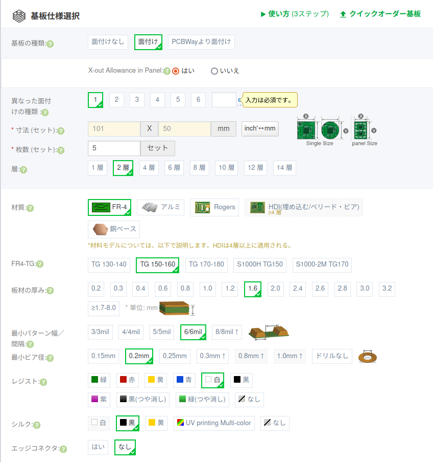
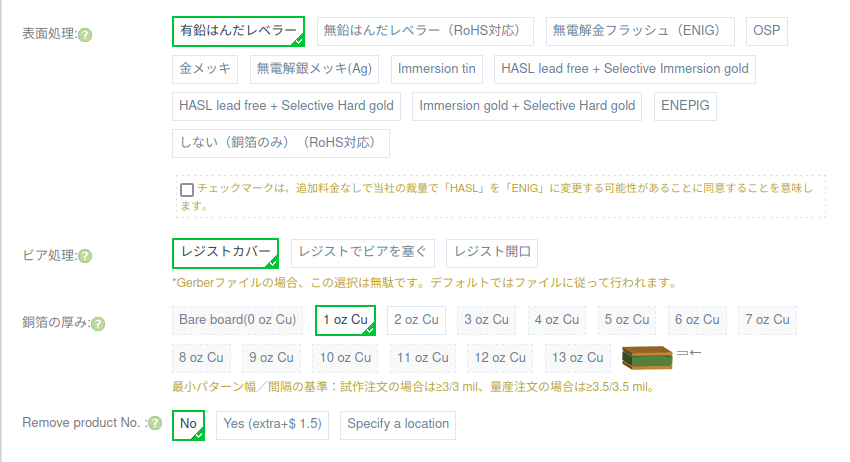
Form
I filled in the form as follows.
Finally, the order is in the review status.
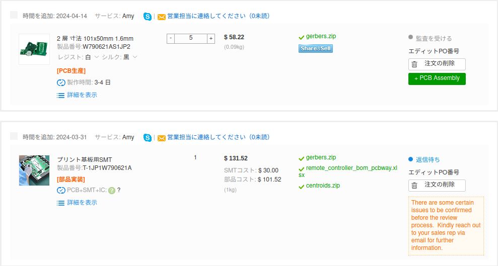
Review from PCBWay
The following is a detailed review from PCBWay. Thanks to them, finally my PCB worked.
- The wrong capacitor value was designated on the BOM purchase list.
- The number of resisters was wrong on the BOM.
- The component size designated on the BOM was wrong (0402 -> 0603).
- The board type designation was wrong “Panel by Customer” -> “Single-board design”.
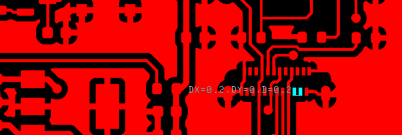
- Some gaps in the IC pins were too small to make the solder mask bridges. -> Did not install solder mask for the pins.
- The switches SW1 ~ SW10 were missed from the centroid file.
Schedule
| Date | Description |
| 2024/3/31 | Start ordering |
| 2024/5/7 | Start assembling after technical reviews |
| 2024/5/28 | The PCB was shipped |
| 2024/6/8 | PCB arrival |
Operational check
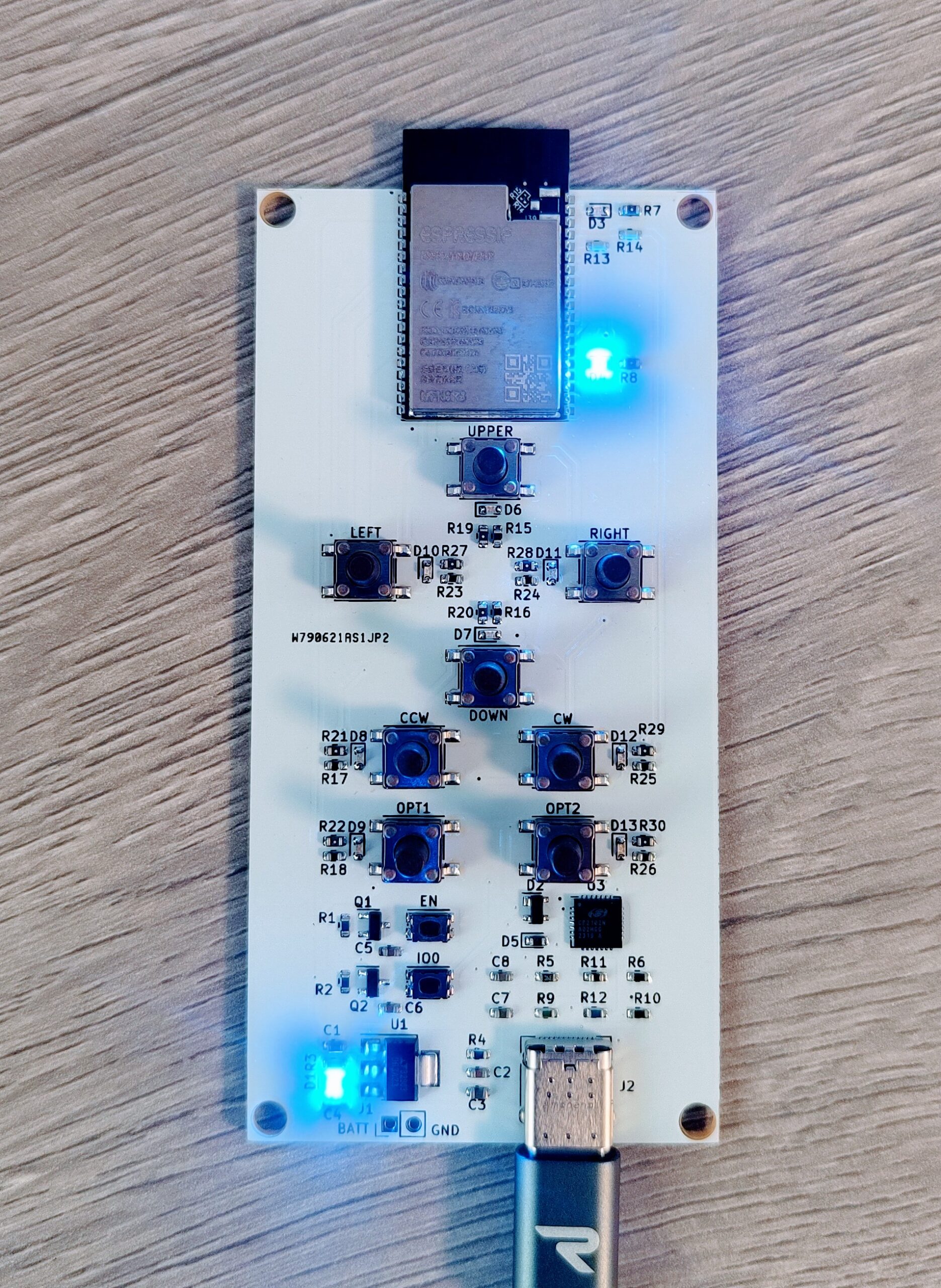
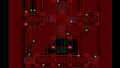
It worked fine as in the following picture and movie!!! The top-right LED and the LEDs adjacent to the switches turn on when the switches are pressed.
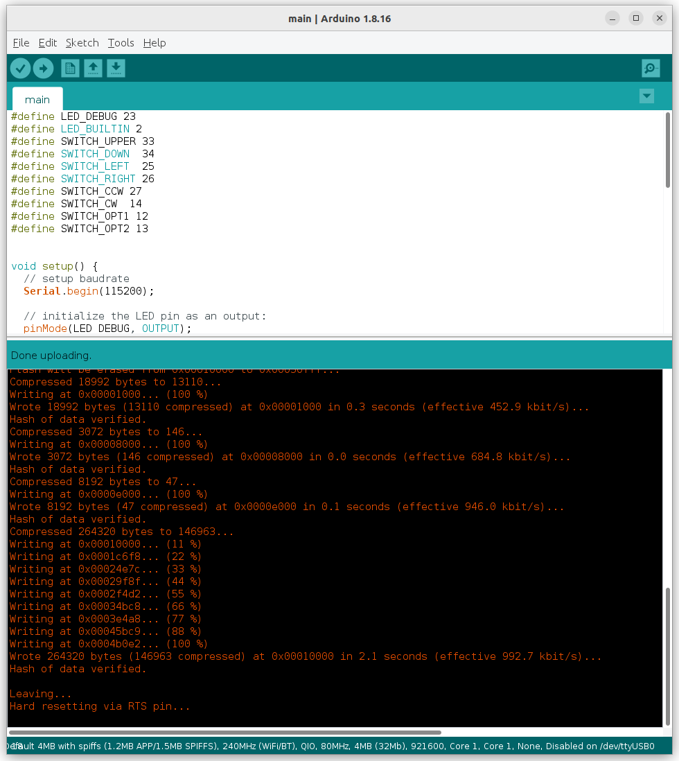
Also, succeeded in writing software on the board (The code is here).
Summary
Many thanks to PCBWay, I have gotten the PCB for a remote controller. I will try to design the PCB for an omni-wheel robot shortly.
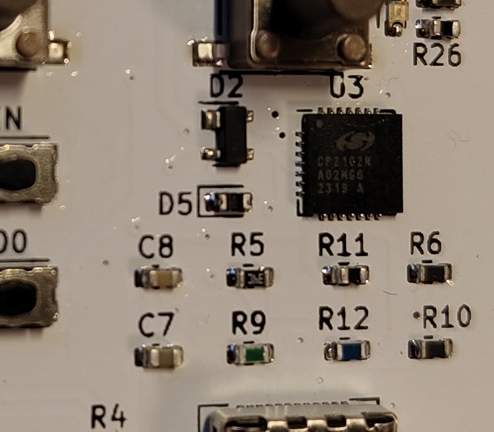
Soldering was also beautiful.
コメント