Using the h-bridge circuit, we rotate a motor in the clockwise and counter-clockwise direction. In the previous article, PWM control of a motor through STM32 has already been tested.
H-bridge explanation
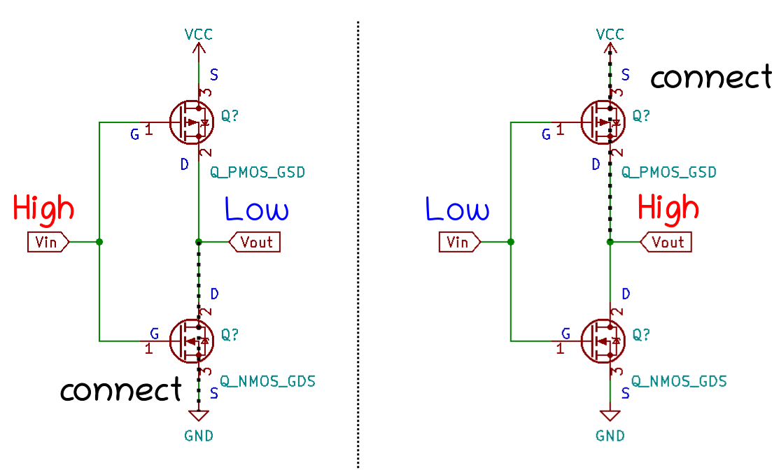
Basically, P-MOSFET draws current from the source to the drain while N-MOSFET allows current flow from the drain to the source when they are ON.
For reference, we can think of the following circuit called CMOS inverter. Vout should be LOW when Vin is HIGH and Vout is HIGH if Vin is LOW. The threshold for determining whether Vin is HIGH / LOW is approximately Vcc/2 (ref.
Taking this into account, there are 4 cases to be considered.
| PWM 1 | PWM 2 | rotation |
| LOW | LOW | brake |
| HIGH | LOW | rotate |
| LOW | HIGH | reverse rotation |
| HIGH | HIGH | stop |
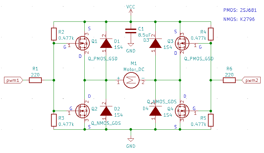
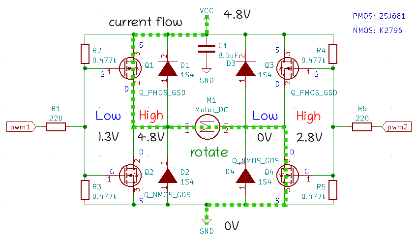
Our h-bridge circuit is described as follows.
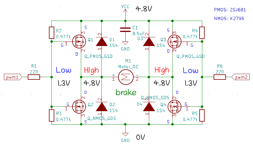
The first case is both PWM 1 and PWM 2 are LOW, thus the outputs of the CMOS inverter circuits are HIGH. This results in a brake condition for the motor.
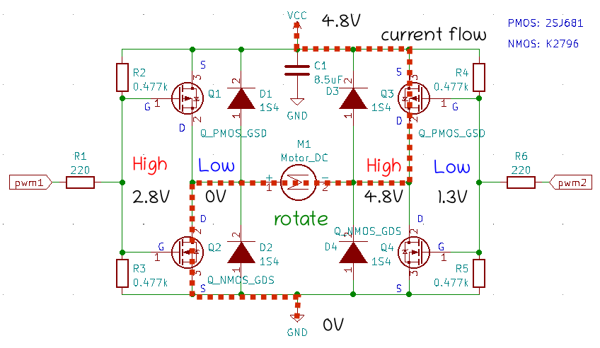
In the PWM 1 HIGH and the PWM 2 LOW case, the current flow is depicted as follows and the motor rotates.
The motor reverses its rotation when the PWM 1 is LOW and the PWM 2 is HIGH.
High voltage input from both PWM 1 and PWM 2 results in a stop condition.

The voltages are measured by sanwa multimeter.
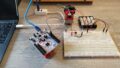
Hardware
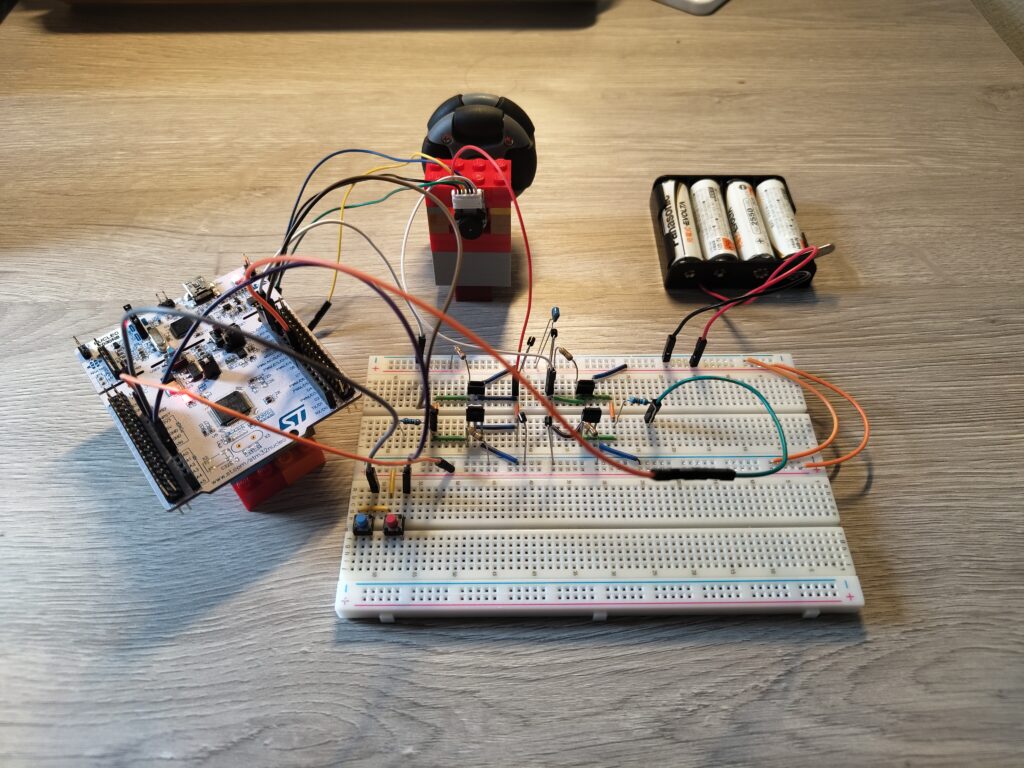
Used two tactile switches for controlling the rotational direction of a motor. When you press the blue switch, the motor rotates counter-clockwise. Pressing the red one makes it rotate clockwise.
Setup
As in the previous article, the following setup is used.
| host PC | DELL XPS 13 |
| host OS | ubuntu 22.04 |
| IDE | STM32CubeIDE 1.13.1 |
| microcontroller | NUCLEO STM32 F030R8T6 |
Circuit
The circuit schematic is here on github!
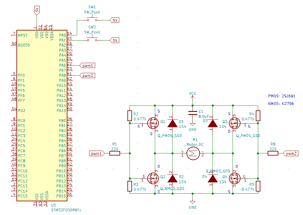
Transistors, registers, a capacitor, and diodes configurations are as follows. Diodes and a capacitor are installed for circuit protection.
| Nch mosfet | K2796 | 2 pieces |
| Pch mosfet | 2SJ681 | 2 pcs |
| gate resistor | $220 \, \mathrm{\Omega}$ | 2 pcs |
| gate to source resistor | $0.477 \, \mathrm{k \Omega}$ | 4 pcs |
| capacitor | $8.5 \, \mathrm{\mu F}$ | 1 piece |
| tactile switch | – | 2 pcs |
| diode | S4 | 4 pcs |
| motor | GB12-N20B (chosen in this article) | 1 pc |
| AA battery (単3電池) | Panasonic EVOLTA | 4 pcs |
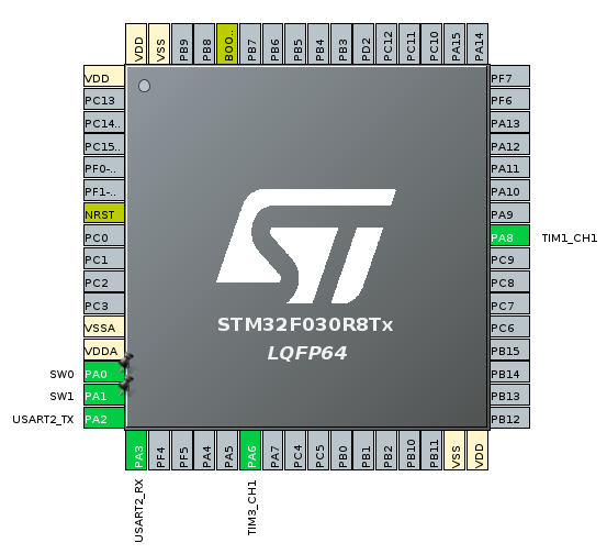
The following diagram shows the PIN layout of NUCLEO-F030R8.
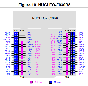
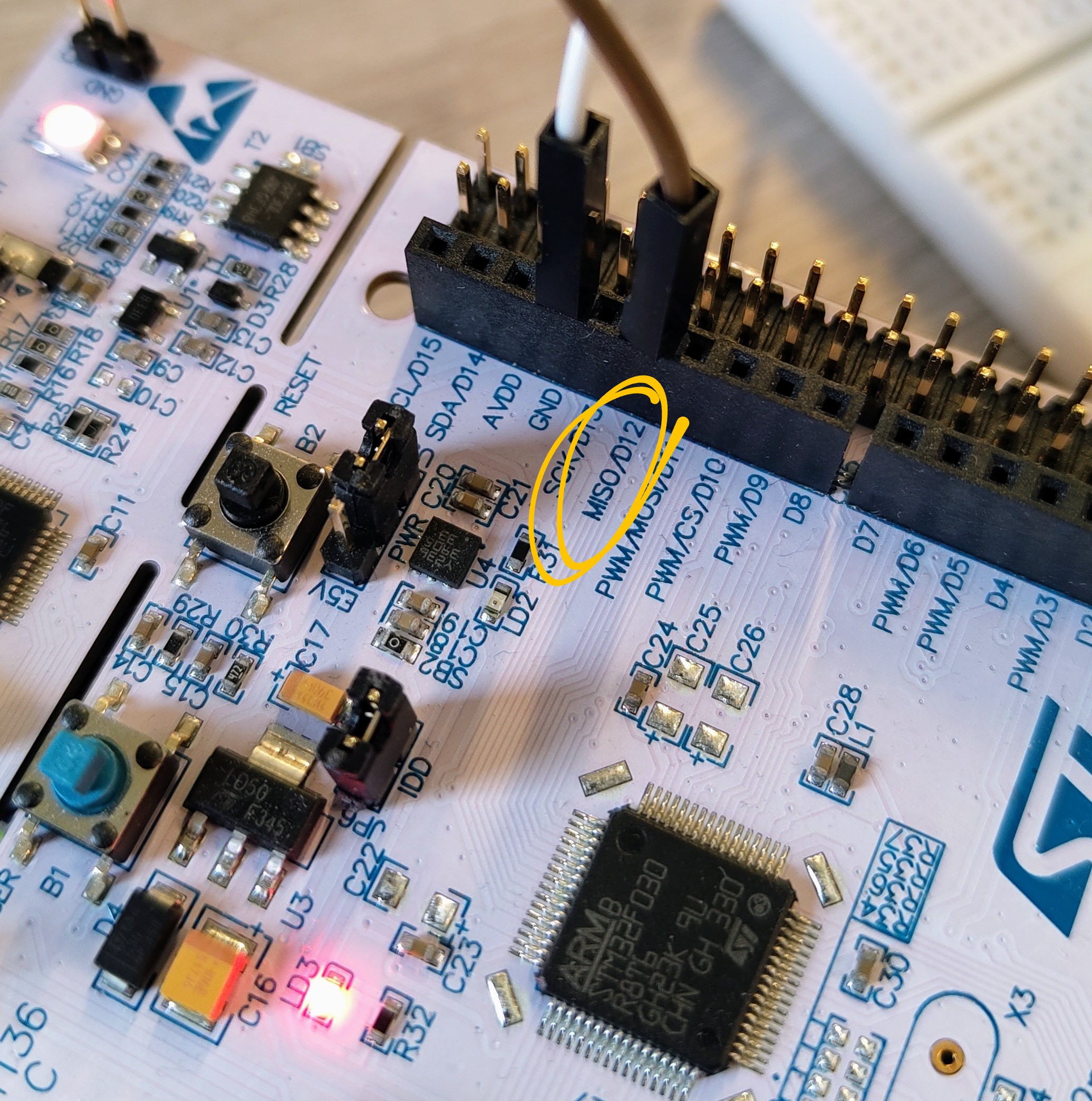
We use 4 PINs this time and each PIN has the following role.
| GPIO | PIN | role |
| PA0 | A0 | input for tactile switch blue |
| PA1 | A1 | input for tactile switch red |
| PA8 | D7 | PWM 2: Timer 1 channel 1 |
| PA6 | D12 | PWM 1: Timer 3 channel 1 |
In order to power up STM32, 5V PIN is connected to the battery whose voltage is approximately 5V.
Software
GPIO configuration (setting of .ioc file)
Utilize timer 1 channel 1 and timer 3 channel 1 for PWM output and GPIO input for tactile switches.
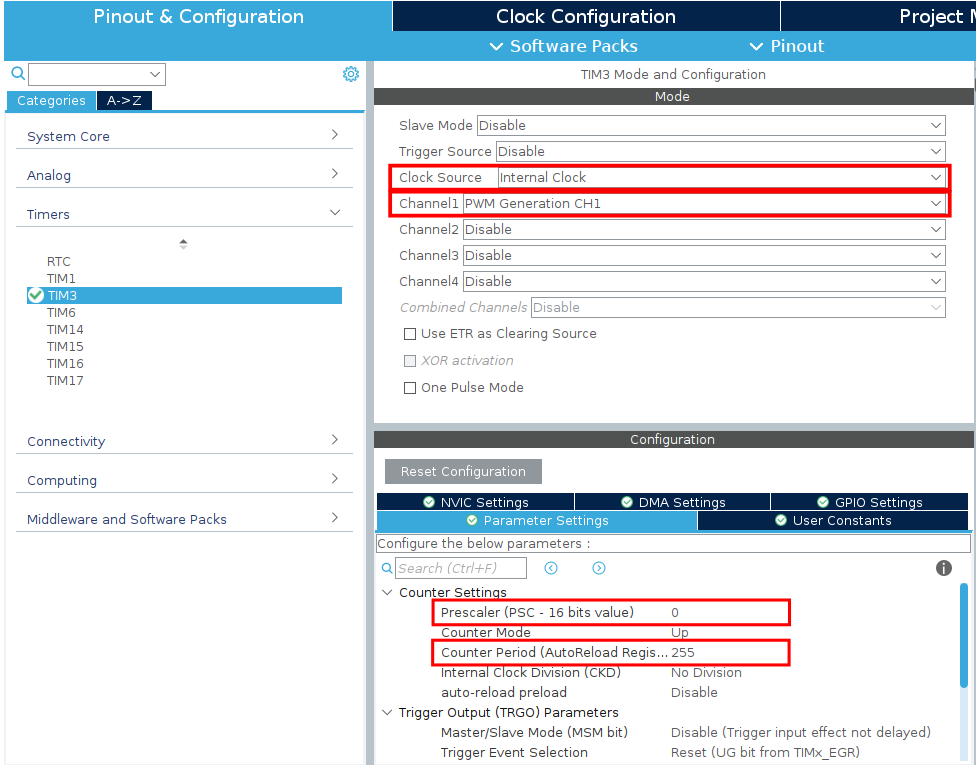
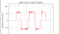
Output for Motor PWM
As in the previous article, we set the PWM configuration of timer 3 ch 1 as follows. I adopt the same configuration to timer 1 ch 1.
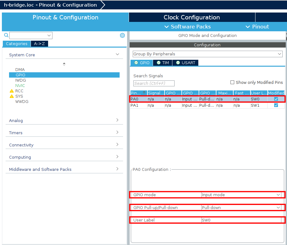
Input from tactile switch
Both GPIO inputs introduce GPIO pull-down resistors. Those PINs are labeled as SW0 and SW1, respectively. Since we use pull-down resistors, a HIGH signal comes when the button is pressed and a LOW signal comes when it is not pressed.
Source code
User defined part is very simple. I added the following code for activating the motor. The full source code is uploaded here on github.
  /* USER CODE BEGIN 2 */
  HAL_TIM_PWM_Start(&htim1, TIM_CHANNEL_1);
  HAL_TIM_PWM_Start(&htim3, TIM_CHANNEL_1);
  /* USER CODE END 2 */

  /* Infinite loop */
  /* USER CODE BEGIN WHILE */
  while (1)
  {
	uint8_t button_state0 = HAL_GPIO_ReadPin(SW0_GPIO_Port,SW0_Pin);
	uint8_t button_state1 = HAL_GPIO_ReadPin(SW1_GPIO_Port,SW1_Pin);

	if (button_state0 == 1) {
		__HAL_TIM_SET_COMPARE(&htim1, TIM_CHANNEL_1, 255);
	} else {
		__HAL_TIM_SET_COMPARE(&htim1, TIM_CHANNEL_1, 0);
	}

	if (button_state1 == 1) {
		__HAL_TIM_SET_COMPARE(&htim3, TIM_CHANNEL_1, 255);
	} else {
		__HAL_TIM_SET_COMPARE(&htim3, TIM_CHANNEL_1, 0);
	}
    /* USER CODE END WHILE */

    /* USER CODE BEGIN 3 */
}- starting PWM outputs
- read GPIO values of the tactile switches
- depending on the values, change PWM outputs
As a result, when none of the switches are pressed, the motor acts as a brake, rotating counter-clockwise when the blue switch is pressed and clockwise when the red switch is pressed.
コメント