Read encoder values
We use a GA12-N20 motor whose PPR (pulse per revolution) is $7$ (ref). The velocity of a motor is derived by applying the following equation (ref)
\begin{align}
\mathrm{velocity} [\mathrm{rpm}] = 60 \times \frac{\mathrm{encoder \ value}}{\mathrm{interval}} \times \frac{1}{\mathrm{PPR} \times \mathrm{gear \ ratio} \times \mathrm{encoder \ number}}
\end{align}
with
- PPR: $7$
- gear ratio: $100$
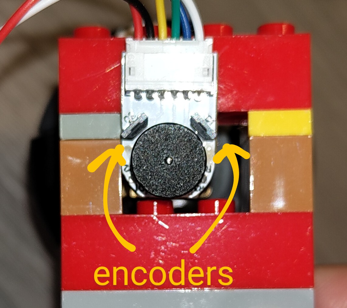
- encoder number: $2$ (This motor has two encoders).
Here, the measurement timer frequency and the interval is determined as follows (ref).
\begin{align}
\mathrm{frequency} &= \frac{\mathrm{frequency \ of \ the \ clock}}{\mathrm{prescaler} \times \mathrm{counter \ period}} \\
\mathrm{interval} &= \frac{1}{\mathrm{frequency}}
\end{align}
with
- frequency of the clock: $8,000,000 \ \mathrm{Hz}$
- prescaler: $10$
- counter period: $8,000$
The frequency is $100 \ \mathrm{Hz}$ and the interval is $10 \ \mathrm{ms}$.
Hardware setup
These are configurations for the experimental equipment.
| equipment | detail |
| host PC | DELL XPS 13 |
| host OS | ubuntu 22.04 |
| IDE | STM32CubeIDE 1.13.1 |
| microcontroller | NUCLEO STM32 F030R8T6 |
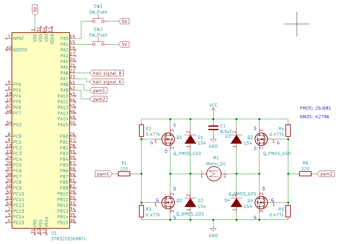
The circuit configuration is as follows.
| parts | detail | number |
| Nch MOSFET | K2796 | 2 pieces |
| Pch MOSFET | 2SJ681 | 2 pcs |
| gate resistor | $220 \, \mathrm{\Omega}$ | 2 pcs |
| gate to source resistor | $0.477 \, \mathrm{k \Omega}$ | 4 pcs |
| capacitor | $8.5 \, \mathrm{\mu F}$ | 1 piece |
| tactile switch | – | 2 pcs |
| diode | S4 | 4 pcs |
| motor | GB12-N20B (chosen in this article) | 1 pc |
| AA battery (単3電池) | Panasonic EVOLTA | 4 pcs |
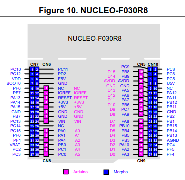
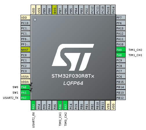
We use 6 PINs and each PIN has the following role.
| GPIO | PIN | role |
| PA0 | A0 | input for tactile switch blue |
| PA1 | A1 | input for tactile switch red |
| PA8 | D7 | Timer 1 channel 1: PWM for motor |
| PA9 | D8 | Timer 1 channel 2: PWM for motor |
| PA6 | D12 | Timer 3 channel 1: read encoder value from hall signal B |
| PA7 | D11 | Timer 3 channel 2: read encoder value from hall signal A |
From the website, the wiring pattern is shown below.
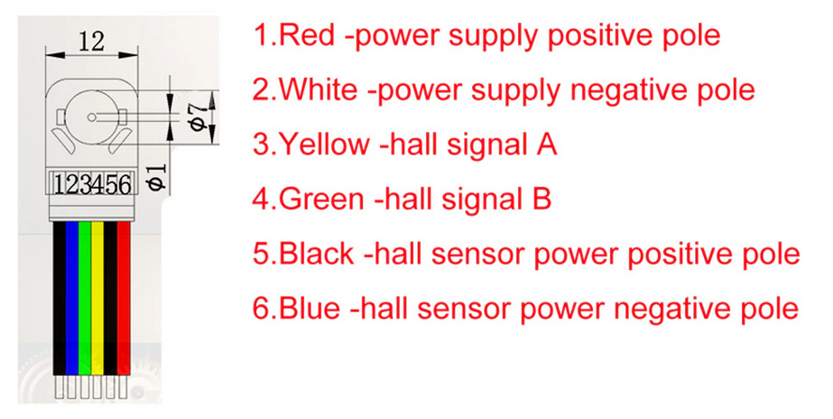
STM32CubeIDE and Kicad view should help your understanding.
Software configuration
Overall source codes can be found here.
Timer usage
Each timer has the following role.
- Timer 1: PWM signal generation
- Timer 3: Acquire encoder value
- Timer 6: A basic timer for control and measurement
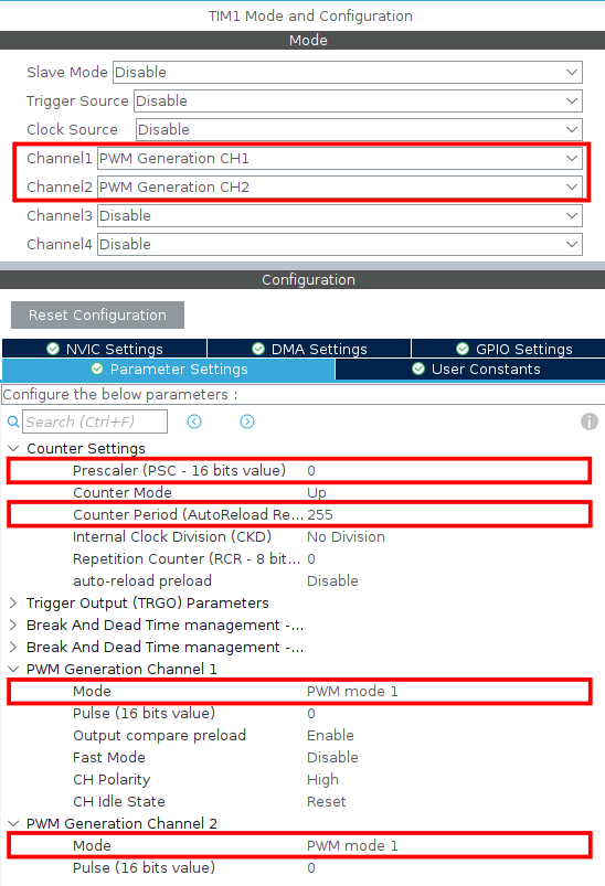
Timer 1
The following configuration is adopted. According to the counter period (ARR: Auto reload register value), the maximum value of the CCR is 255.
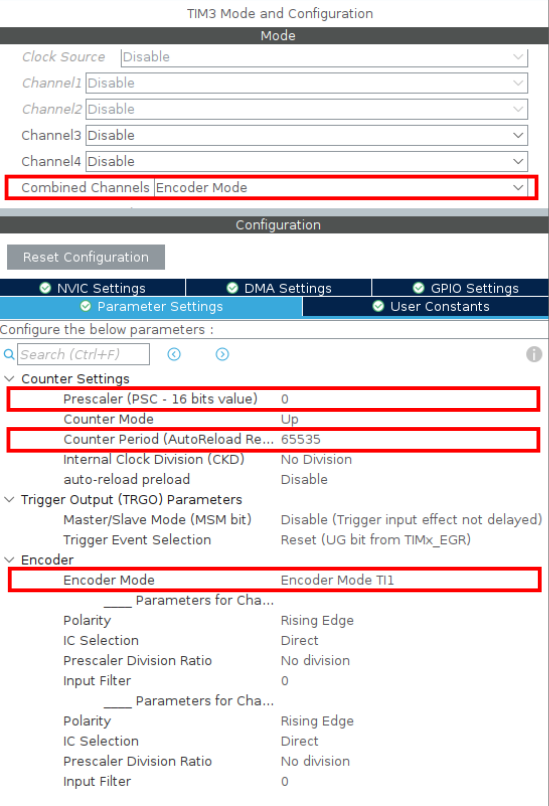
Timer 3
We use the encoder mode for timer 3 and measure the encoder value.
The following video explains the usage of encoder mode for STM32 timers. It explains that using this mode is very useful in terms of avoiding the jitter of the encoder.
Adopt the default prescaler and counter period and we check only TI1 trigger (not TI2).
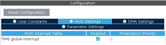
Timer 6
In order to achieve $100 \ \mathrm{Hz}$, the prescaler and the counter period are set as follows.
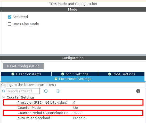
Timer 6 is a basic timer that periodically measures the rotational speed of the motor and calculates the PWM command. We dig into read_encoder_count(), calculate_rpm(), and control_motor_when_button_pressed() function more in the next section.
void HAL_TIM_PeriodElapsedCallback(TIM_HandleTypeDef *htim)
{
	if ( htim == &htim6 )
    {
		int enc_count = read_encoder_count();
		int target_rpm = 60;
		int measured_rpm = calculate_rpm(enc_count);
		printf("%d\n\r", measured_rpm);

		control_motor_when_button_pressed(target_rpm, measured_rpm);
    }
}
Function explanation
int read_encoder_count (void)
int read_encoder_count(void)
{
  int enc_buff = (int16_t) TIM3->CNT;
  TIM3->CNT = 0;
  return enc_buff;
}
This function gets the encoder value and sets the value as zero. By doing this and divide by the interval, we can get the rotational velocity of the wheel.
TIM3->CNT is originally an unsigned 32 bit integer. Converting this into a signed integer results in a negative value when the motor rotates in a counter-clockwise direction.
int calculate_rpm(int timer_count)
int calculate_rpm(int timer_count)
{
	// motor specification
	const int PPR = 7;
	const int encoder_num = 2;
	const int gear_ratio = 100;

	// timer specification
	const int prescaler = htim6.Init.Prescaler + 1;
	const int period = htim6.Init.Period + 1;
	const int clock_frequency = HAL_RCC_GetPCLK1Freq();
	const double frequency = (double) clock_frequency / ((double) prescaler * period);
	const double interval = 1.0 / frequency;

	// rpm calculation
	const double timer_count_in_1s = (double) timer_count / interval;
	const int measured_rpm = (60 * timer_count_in_1s) / (PPR * gear_ratio * encoder_num);
	return measured_rpm;
}
Utilizing these equations gives us the measured rotational velocity [rpm].
\begin{align}
\mathrm{velocity} [\mathrm{rpm}] &= 60 \times \frac{\mathrm{encoder \ value}}{\mathrm{interval}} \times \frac{1}{\mathrm{PPR} \times \mathrm{gear \ ratio} \times \mathrm{encoder \ number}} \\
\mathrm{frequency} &= \frac{\mathrm{frequency \ of \ the \ clock}}{\mathrm{prescaler} \times \mathrm{counter \ period}} \\
\mathrm{interval} &= \frac{1}{\mathrm{frequency}}
\end{align}
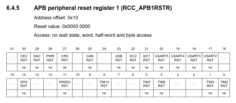
Timer 6 uses APB1 clock as shown below and the frequency is acquired by the API HAL_RCC_GetPCLK1Freq() (ref).
int calculate_pid_cmd(int target_rpm, int measured_rpm)
PI control for the motor is implemented here. The target velocity [rpm] and measured velocity [rpm] are compared. A feed-forward term is added for stable motion. We adopt saturation for the integral term and the command.
int calculate_pid_cmd(int target_rpm, int measured_rpm)
{
	// pid gain and parameter
  	const int kp = 1;
  	const int ki = 1;
  	const int ff = 100;
  	const int max_ei  = 300;
  	const int max_cmd = 255;

  	// deviation calculation
  	const int e = target_rpm - abs(measured_rpm);
  	ei_ += e;
  	ei_ = max(min(ei_, max_ei), -max_ei);

  	// command calculation
  	int cmd = kp * e + ki * ei_ + ff;
  	cmd = max(min(max_cmd, cmd), 0);

  	return cmd;
}
void control_motor_when_button_pressed(int target_rpm, const int measured_rpm)
Depending on which button is pressed, the motor can change the rotational direction.
void control_motor_when_button_pressed(int target_rpm, const int measured_rpm)
{
	// check button states
	const uint8_t button_state0 = HAL_GPIO_ReadPin(SW0_GPIO_Port, SW0_Pin);
  	const uint8_t button_state1 = HAL_GPIO_ReadPin(SW1_GPIO_Port, SW1_Pin);

  	// calculate pid command
  	target_rpm = button_state0 != button_state1 ? target_rpm : 0;
  	const int cmd = calculate_pid_cmd(target_rpm, measured_rpm);

  	// blue button: clockwise
  	if (button_state0 == 1) __HAL_TIM_SET_COMPARE(&htim1, TIM_CHANNEL_1, cmd);
  	else __HAL_TIM_SET_COMPARE(&htim1, TIM_CHANNEL_1, 0);

  	// red button: counter-clockwise
  	if (button_state1 == 1) __HAL_TIM_SET_COMPARE(&htim1, TIM_CHANNEL_2, cmd);
  	else __HAL_TIM_SET_COMPARE(&htim1, TIM_CHANNEL_2, 0);
}
Control performance
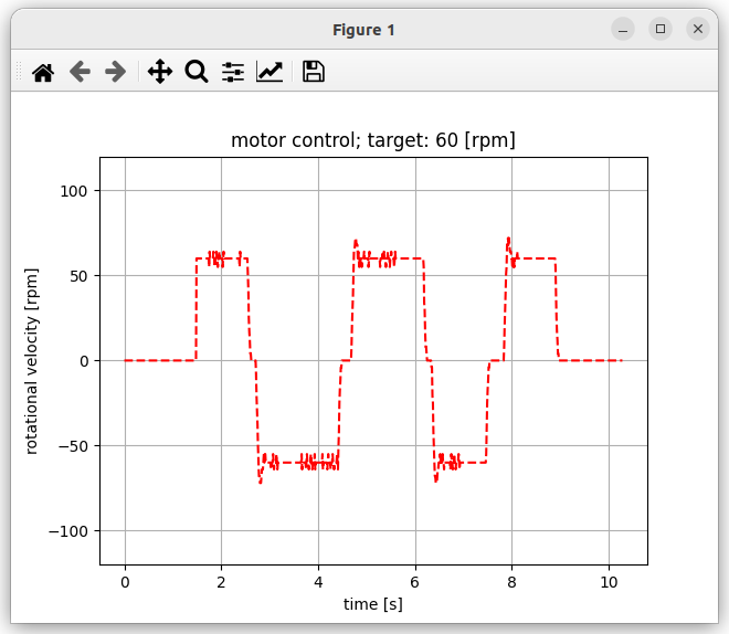
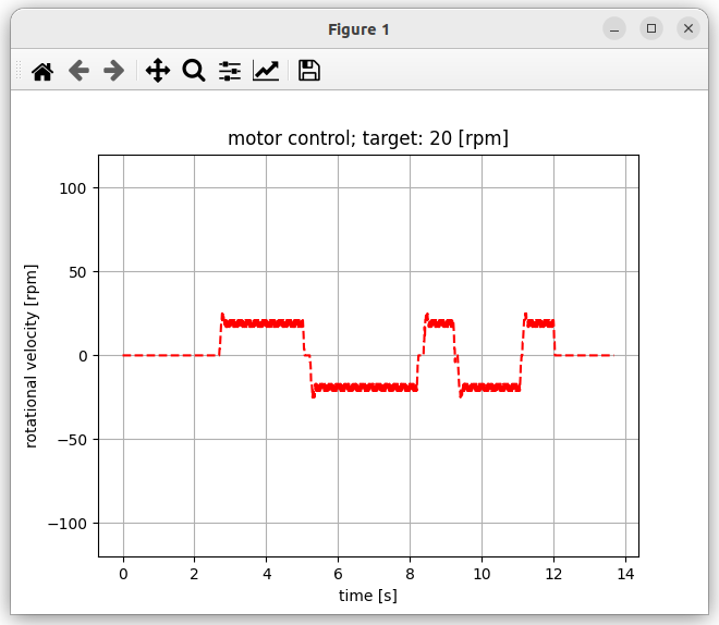
The rotational velocity graphs of a motor are as follows.
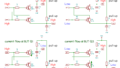
Target velocity is 20 [rpm] case
Target velocity is 60 [rpm] case

Target velocity is 100 [rpm] case
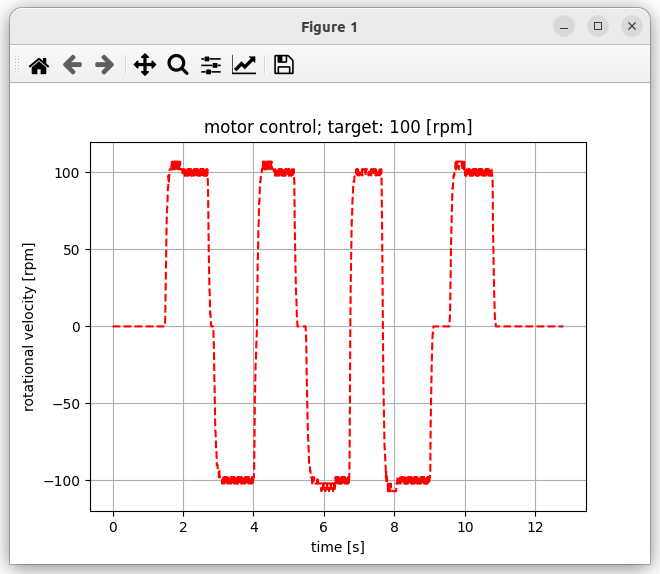
In either case, the graph plots show that the result was pretty good though there is a bit overshoot.
Tips for plotting data
SWV (Serial Wire Viewer)
Unfortunately, I could not use this method since our module is using cortex m0.
SWV options is not available and not work with Cortex-M0.
How do I enable SWV in my STM32Cube ide?
printf to COM port + Python data plot
I used Python for plotting data. For data collection, I used the following command referring to this site.
stdbuf -o0 cat /dev/ttyACM1 > rpm_data.logUsed the following very simple Python code for data plot (ref).
import pandas as pd
import matplotlib.pyplot as plt

data = pd.read_csv('rpm_data.log',sep='\s+',header=None)
data = pd.DataFrame(data)
y = data[0][400:]
x = range(len(y))
t = []
for i in x:
    i *= 0.01    # data acquired in 100Hz
    t.append(i)

plt.plot(t, y, 'r--')
plt.title("motor control; target: 60 [rpm]")
plt.xlabel("time [s]")
plt.ylabel("rotational velocity [rpm]")
plt.ylim(-120, 120)
plt.grid()
plt.show()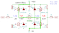
コメント